Control and collide different frequencies together.
Re-create the Hutchison Effect
Re-create anti-gratity, reach zero point.
Open new dimensions
Teleportation
Disintigrate materials(garbage, old buildings, etc.).
Make new materials(harder, tuffer, more elastic)
Give people free energy
Create new type of generator
New type of wirless current, not AC, not DC, but CC for continuing current.
CHANGE THE WORLD!!!


Here is original schematic of coil

#1 NST 15kV 60mA, 900Watts
#2 chokes - 1.5" tall, 43 windings on a 2.375 dia pvc tube

previous chokes, 8" tall, 241 turns

#3 Flexi Gap, Spark Gap, set with 6 gaps right now, gapping is at .120 each gap before flexing, I would have to check gap sizes at this point.
view from other side of transformer
#4 Capacitor. (6)Alum plates at 6" by 6", 36" total area, (7) sheets of standard window type glass, at .220 thick, dielectric constant is between 4.2 to 8....so I used 6 as the constant. I calculate Farads to be at 1097pF or 1.097nF or .00109uF. 


special homemade clamps
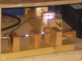
#5 Duel Gap spark gap. (2)Gaps are at a spacing of .562 each, I'm not sure what resistance would be.

#6 Primary Coil. made of 60 feet of 1/2 dia copper tubing, Spacing =.500, primary hole dia=10", primary total dia=32". Primary is also elevated up about 16" from bottom of secondary coil at this time. I calculate inductance at:
11 turns= 59.9 uH
10 turns= 48.8 uH
9 turns= 38.5 uH
8 turns= 29.9 uH
7 turns= 22.6 uH
6 turns= 16.4 uH
5 turns= 11.4 uH
4 turns= 7.3 uH
3 turns= 4.2 uH
2 turns= 2 uH

#7 Secondary Coil. height=44.812", turns= 1300, PVC form dia=5.562. I calculate inductace to be at 26uH, and capacitance at 15.48pF

#8 Top Load Toroid. Ring dia=8". Overall dia=25. I calculate capacitace at 27.85pF


With secondary with top load together I calculate resonant frequency at 149.96 kHz
If I calculate secondary as a height of about 28" tall because of primary being elevated at 16" above the bottom of secondary...than resonant frequency would be 204.54 kHz.
Right now Im adjusting all gaps so that fireing is smooth, than I will try to tune 1 more time, than maybe I will lower primary back down to bottom of secondary and try to tune once again, if still no luck I will need to make a pulse generator and frequency counter and do further testing.
New flexi-Multi-Gaps(i have 2 of these)

Some other photos


Replaced home made glass plate capacitor with this High Voltage Pulse Capacitor.
Here is data on this capacitor... http://www.alltronics.com/cgi-bin/category.cgi?item=20P005
Added a Variac
Moved Primary coil back down.

RESULTS: I now get 1 single strong discharge/spark from my primary gaps every time I power up the system, and that's it, nothing else!
HMMM: Maybe I have the input or output conections to the filter wrong? Or maybe I got the wrong type of capacitor in my system?
NEXT: I will replace High Voltage Pulse capacitor with a transmitting mica type capacitor(g3 or g4 type) as John Hutchison suggests. http://www.fairradio.com/catalog.php?mode=view&categoryid=966
I will continue to keep everone informed of progress!
This is my company
Here are a few referances I used.
capacitor calculator http://www.csgnetwork.com/parapltcapcalc.html
the tesla coil designer http://www.noonco.com/tesla/index.html
Tesla coil calculator http://www.classictesla.com/java/calculat.html
Teslamap5(good program) http://teslamap.com/
Another good tool http://www.classictesla.com/java/javatc.htmlCapacitor calculator http://www.csgnetwork.com/parapltcapcalc.html
THANKS:
Thank You Nikola Tesla.
Special thanks to John K. Hutchison for all his help in making these coils a reality, and he has been a great insperation to me.
Thanks to Newton2 for many sketches and design ideas.
Thanks to Harvey and others for their great support.Thanks to R.M. tool for donating time, money and many manufacturing parts.
FREE ENERGY

Ground wire connects off of circuit, from inbetween 2 large electrolytic capacitors.
4) .1 micro Farads ceramic disk capacitors
2) 100. micro Farads electrolytic polorized capacitors
4) germanium diodes (1N34A)(mouser# 526-1N34A)
diodes can be found here at mouser, these are the one that i use..... http://www.mouser.com/Search/Refine.aspx?Keyword=1n34
i see that there are a few types of germanium diodes out there, the ones i get from mouser are rated at Peek Reverse Voltage 75V
here is another website that has good picture of them...but not sure if they are exactly the same ratings.
https://www.micro-tools.com/store/item_detail.aspx?ItemCode=1N34A
here is a website that has specifications on some of the differant types... http://www.datasheetcatalog.com/datasheets_pdf/1/N/3/4/1N34A.shtml
If you decide to use 2 circuits, i just connect their outputs together...neg output from first circuit to neg output of second circuit & pos output from first circuit to pos output of second circuit.
And take readings from same place....from where you conected the 2 circuits together.

Free Counter


